My favorite activity in the world is flying
radio-controlled combat gliders. These are typically 48 inch flying
wings that are nearly indestructible. Here is Here is
a nice video of a large group of Colorado pilots battling it out on a good day.
We have a good sized group of RC combat glider pilots who fly in
Pacifica California
during the excellent summer winds that we generally get between June
and September. Most pilots use commercial glider kits such as the Zagi,
Combat Wings, and the Bee. These are all very good planes but the
sport has progressed such that you have to make a lot of
modifications to make them combat-ready. This caused me to dream about
what the ultimate combat glider should be. I obsessed over this
project for a year and the result appears to be excellent. These are
the plans that I created with all of the features and flying
characteristics that I want in a combat glider. I will try to include
enough information for you to build one yourself. My criteria are:
48 inch wing span which is the most common size and
which I feel is not too large that it lumbers, and not too small making
it too sensitive.
Bullet proof materials and construction to stand up to constant punishment.
A relatively low aspect ratio for the excellent self-recovery and nimble aerobatics.
Fast
Having learned from painful experience with my own radical
designs, I now understand why the general plans for flying-wing combat
gliders all look largely the same. With the design of the AR-40 I
chose to stay closer to the proven designs but modified to accommodate
my preferred materials and design constraints.
The first main choice I needed to make was to select the
exact aspect ratio that I wanted. The aspect ratio in its simplest form
is wing span divided by width but a better definition is twice the
wing span divided by the sum of the root chord and tip chord, including the elevon width. Using this formula I measured all of the gliders that my fellow pilots and I have been flying and entered them into
a spreadsheet
to calculate all their aspect ratios. I was then able to sort the list
of gliders by aspect ratio and select the aspect ratio I wanted based
on what I had seen of each glider's performance. The name of this
glider is "AR-40" simply because I chose the aspect ratio of 4.0 as
being my ideal.
Here are the specs.
Note: Optional cut-out for base plate shown in red.
Here is the
Visio drawing file in case you want to edit it.
The main unusual feature of this design is the single large,
unbreakable carbon fiber spar that runs from tip to tip. This allows
the glider to retain as much energy as possible through high-G turns
and still be flexible enough to absorb the force of hard collisions and
landings. In order to keep the entire length of the spar within the
foam core I needed to reduce the amount of sweep. This makes it a bit
less stable in pitch. This much is not a problem for experienced pilots
but is probably not ideal for beginners. Another potential
disadvantage of this choice is that the spar and the glue to hold it
are placed well behind the center of gravity. That means that
substantial weight will need to be added forward of the CG to
compensate and that guarantees that in order to fly well, the resulting
plane will be quite heavy for its size. Again, that is not a big
problem for experienced pilots but increases the speed and danger to
people and the plane. I bought the
rod #020099 from Goodwinds.com with a .281" outer diameter, .186 inner diameter.
I had the wing cut with a computer-controlled cutting machine by the helpful folks at
FlyingFoam.com. If
you send them the above specifications and diagram, they can cut and
send you the cores for about the same price as a commercial glider kit.
I also recommend that experienced pilots experiment with your own
ideas using mine as a starting point. If you don't do anything crazy
you should be OK and you may even improve on the design.
Note that from here on, I'll give a complete describing of
how I built it out, but if you have a preferred materials and methods
of building out a combat glider, then you can stop here. The most
important things are the core cutting parameters and the carbon spar.
All the rest are minor details.
The other main bit of strengthening that I use is the base
plate shown in red above. I use 1/8" hobby plywood glued directly to
the foam. The folks at Flying Foam can cut the spar hole as well as the
base plate cut-out, which is a huge help. The cut-out gives you a
nice flat surface on which to attach the base plate. In addition to
stiffening the typically weak central region, it provides a nice
foundation on which to attach all of your components. I bolted the
servos and battery directly to the plate though you can use servo tape
or other means. It also allows you to easily cut out and transfer all
the components into future planes once your first one needs a body
transplant.
This image shows the cut-out. Just reattach the portions that you don't remove.
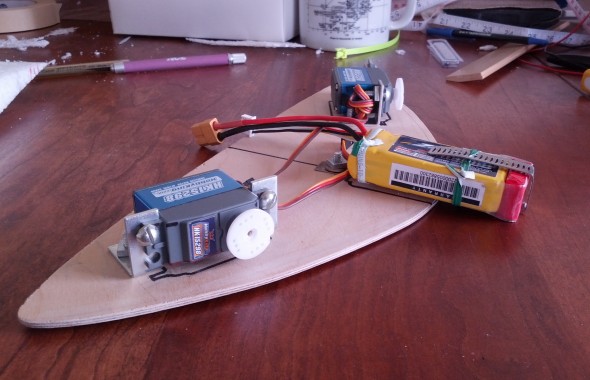
This shows the main components attached:
And this shows how the final assembly will look:
My servos are very strong and fast. They're also
$20 each at Hobby King
which is expensive compared to other components but cheap for what you
get. You can easily get away with less if you want to save money. I
originally used a
lipo battery and
UBEC unit
above but had lots of trouble with them (no fires as some worried) and
do not recommend them. I later replaced it with a 5-cell NiMh. Hobby
King also has
really cheap Spektrum receivers.
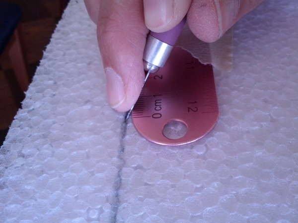
The last bit of foam cutting is to create the trailing edge.
That could have been done by Flying Foam but I wanted to decide later
how and where I want it to be cut. You may want to have them do that
but this operation was very quick and easy. Here you see that I have
taped down a metal ruler and am cutting on a 45 degree angle. Doing
that on top and bottom gives a nice result. The trailing edge ends up
rather fat but that's how the airfoil was designed and I didn't want to
risk modifying it. See the diagram to see what I mean.
The next order of business is to paint the foam. I always
use fluorescent spray paint so that I can more easily spot it in a
crowded fur ball. Contrasting top and bottom designs help to see which
side is up in those crucial moments after a collision.
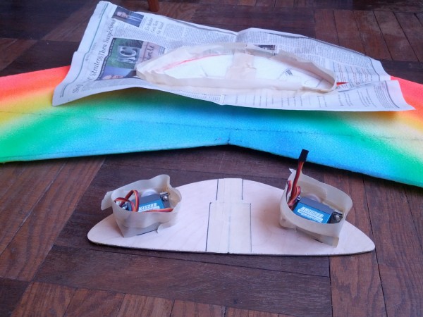
Be sure to paint and save the cut-out foam blocks. You will
want to slice off the topmost painted parts and glue them back in
right before you add the skin.
The secret is to use the very least paint possible so that
the skin adhesive will attach to the foam and not just the paint. Even
knowing that I still used too much paint. You should probably not
paint the foam. Instead, add paint or decals on top of the skin just
to be safe. I'll probably have to iron the skin back down after each
weekend of combat which is unfortunate.
Next up, install the base plate.
I attached the base plate with Super 77 adhesive spray. Here
I have masked off the areas that I do not want to glue in preparation
for spraying. That stuff tends to get all over the place so take your
time and be careful with this step. After spraying, wait a couple of
minutes for it to get tacky and then press it into place with a lot of
pressure.
Next, install the push rods. I highly recommend Golden Rod
or other flexible push rods as they let you place your control horns
close to the center of the elevons, plus the bend keeps your servos
from stripping during collisions. Using the circular servo horns
guarantees that the servo arms won't break either.You may have wondered
why I position the servo horns towards the leading edge and closest
to the center line. This allows the push rods to be bent the least and
for the entire linkage to happen in a small space that is part of the
rectangular servo cut-outs.
Important: Attach the push rods to the bottom-most part of
the servo horn! I.E. closest to the base plate. This is to allow the
push rods to be buried in the foam for as much of its travel as
possible. Here you see where they exit on top and understand why they
connect to the servos near the bottom of the glider.
The skin that I prefer is document lamination plastic. It's
the stuff used on driver's licenses. This stuff is extremely strong
and light and comes with heat-activated adhesive. You use it just like
you would use Monocoat or Ultracoat though you need more heat and
pressure. The thinner rolls will even heat shrink a little which makes
it ring like a bell when you tap it. Mitch who introduced me to this
stuff posted information on our mailing list
here which references an even longer discussion on the
RC Groups forum.
There are two types of plastic "DI" and "CP". The CP type
stretches a bit and is my preference. They also come in a number of
different thicknesses of plastic and adhesive. These are specified as a
fraction with the first number being the thickness of the plastic in
mils (thousandths of an inch) and the second being the thickness of
adhesive. The two numbers must add to 5 or 10. Most builders use 3/2 CP
which is excellent. For the wing above I used 4/6 CP which is one of
the main reasons that it is heavy. I recommend that you get a roll of
3/2 CP. You can get it from
LaminatorWarehouse.com.
though I notice that they don't use the fraction specification
anymore so you should call in your order and make sure you know what
you're getting. You'll want an 18 inch width.This stuff comes in 200
foot rolls which is enough for 10 or 15 gliders, so try to go in on a
roll with some other pilots if you can. The folks at Laminator
Warehouse are very nice. They normally sell rolls in pairs but will
make exceptions for us especially if they already have some broken
sets.
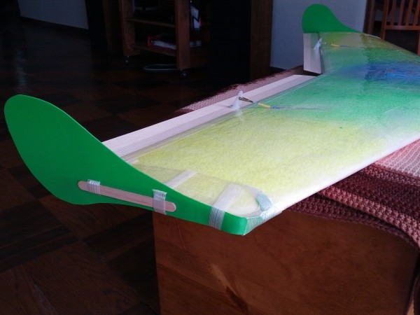
Finally, construct and install the elevens and winglets.
Every builder has their own preferred materials and design for these
parts. My winglets are made from kitty litter containers though large
detergent bottles also work well. Cloroplast is another popular winglet
material as it is very light and cheap but also is easily broken and
torn off in battle.
The popsicle sticks distribute the force across a wide area.
When installed as you see above they almost never break.The
disadvantage of my winglet construction is that it is relatively heavy.
It doesn't weigh very much but since they are at the very back of the
plane, that weight must be compensated with ballast in the nose
meaning that you pay twice for all weight placed behind the CG, and
probably triple for weight at the tips. Therefore any weight that you
can save behind the CG will allow you to build a lighter plane.
Note that I have not yet cut off the tips of the control
horns in the photo above. You can leave them like that while you are
testing which hole you want to attach the push rods to, but be sure to
cut them off once you've decided, otherwise they are easily broken in
collisions and will draw complaints from other pilots if they cut into
their wings.
I've found that typical control horn that most builders use are not
strong enough and will sometimes break off, especially after a lot of
sunlight exposure. My favorite is the beefier Dubro catalog number 237
which I have never broken. You can find them cheaply here.
Note that the base plates for all of the control horns are rather small
which puts a lot of stress on the elavons. My solution is to place a
wider piece of plastic between the control horn foot and the elavon
which spreads out the force. A good source of plastic for that is the
little clips that come with bread and potato bags. Just find one with a wide tab and cut off the clippy parts, leaving you about a one inch square.
The red thing at the front of the battery cage is about 1.7
ounces of lead. That turned out to not be enough in the end and should
have been closer to 3 ounces for the heavy planes that I build. You
want to put all such ballast as far forward as possible but no closer
than about 1.5 inches from the leading edge for your safety and those
around you. The point of adding ballast is to put the center of gravity
where you want it using the least dead weight. Of course a better solution
is to use stronger servos, batteries, or materials,
but usually a small amount of dead weight is needed to get the CG where you like it.
In the diagram above
the CG is meant to be 7.81 inches behind the nose. That means that if
you balance the finished plane on a point or horizontal edge, it will
lie on that line. Even small changes of CG can make a big difference in
how a plane flies. If it is too far back it won't fly at all. If it
is too far forward it will be very sluggish. 7.81 inches is my
preference though beginning pilots will probably be happier with 7.5 or
less. Here is a lovely
CG calculator
on the web that you can use to find out where it should be for the
responsiveness you prefer. Adjust the "CG Position" buttons to suit
your flying skills and preferences. I must emphasize the importance of
choosing a proper CG and carefully adjusting your build to put it
where you want it. That may take a bit of trial and error due to the
weight and placement of all your components and materials but it is
crucial to get the CG right.
Here is what the CG calculator looks like:
See the "responsiveness" control in red above.
Here is the same wing
in centemeters.
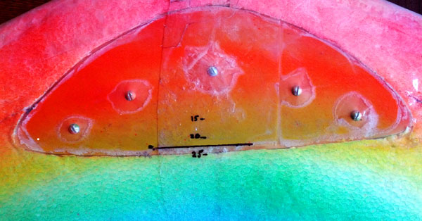
Here is a close-up of the base plate on the underside of the
finished glider with the CG positions marked. The horizontal line is
where I decided that I liked it.
Once getting the CG right I found that roll control was much
more sluggish than pitch. That's true in general but seemed a bit
excessive in this case. I bumped aileron throw to 125% of my
transmitter's default, and all was perfect for my tastes. You will
certainly want to experiment to find your ideal settings.
The Result
Let's see it in action! Here is a video I shot both from the ground and with an on-board camera on a very good day.
The AR-40 turned out much better than I had
hoped! When well-trimmed it has an unusual tendency to continue on a
straight line when you let go of the stick. I was used to planes that
would quickly recover on their own and turn lazy circles. At first
this made me nervous because a lost of radio contact could leave it
flying out to sea or other poor locations, but now I like the
behavior. The plane goes where you point it, so be careful where you
point it!
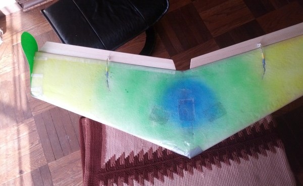
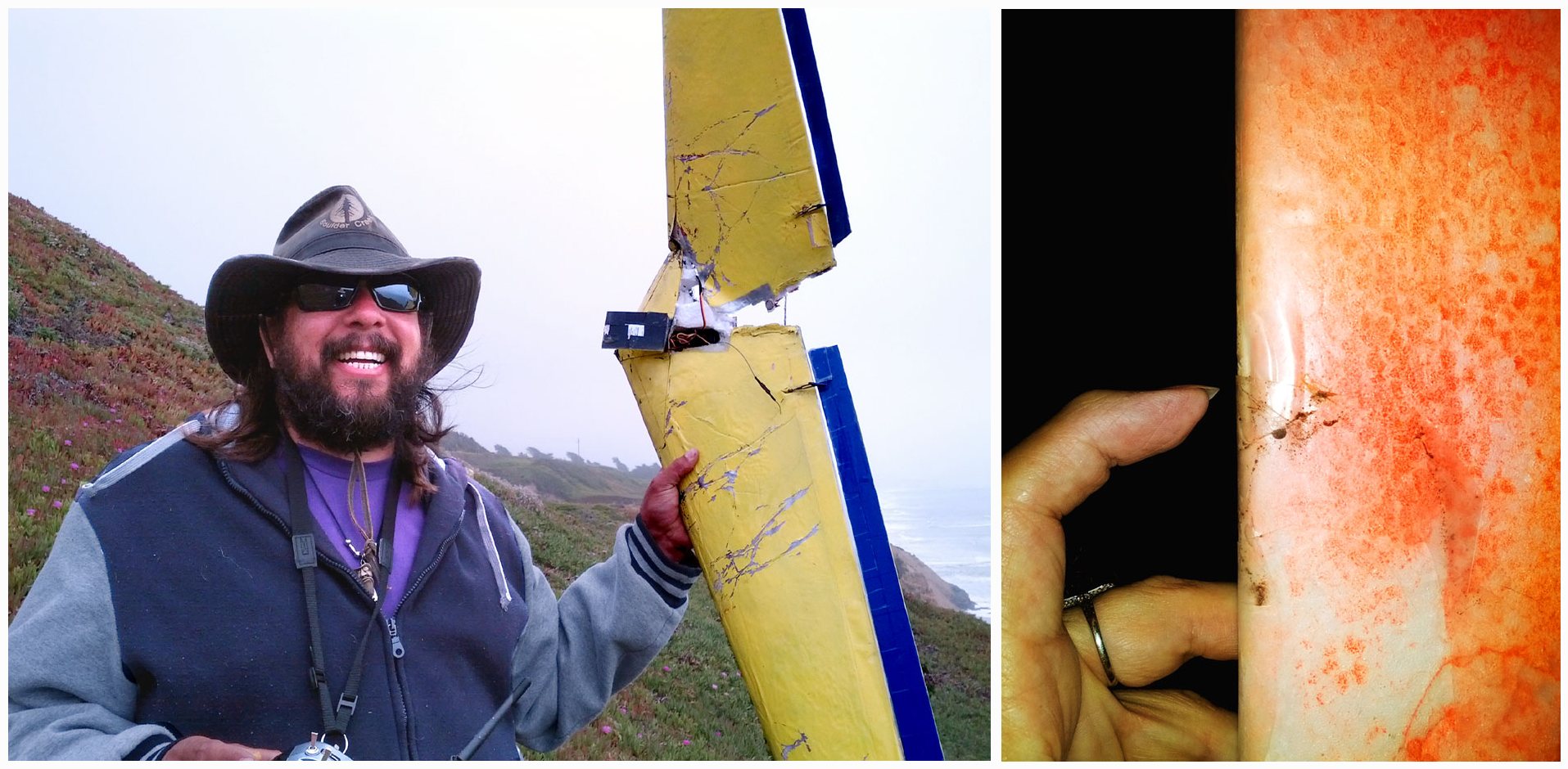
And how does it stand up to combat? Well look what happened
when it met head-on with another glider. That glider was an old
hand-me-down that had been covered in Monocoat or similar skin and it
nearly cut it in two. Notice the damage to my glider on the right.
Believe it or not, Dano's plane was fixed in less than 5 minutes using 3
pieces of fiber tape and thrown back out into the mix where it did
just fine. Of course he'll spend some time later gluing all the foam
back together, and should probably reskin with Docu-lam, though he's
also interested in building an AR-40.
If you build a plane from these plans, please
Let me know. Likewise if you have any questions or corrections.
Well, that's about it. Here's a snap of our happy group mixing it up in Pacifica, California. Happy hunting!